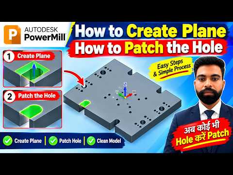
In the world of computer-aided manufacturing (CAM), preparing your 3D model properly is essential for generating smooth, efficient, and collision-free toolpaths. Autodesk PowerMill offers a robust suite of surface modeling tools designed to help machinists and programmers refine geometry before generating CNC code. Among these essential tasks, creating custom planes and patching surface holes are fundamental skills that every programmer should master.
In this step-by-step guide, we will explore why these techniques matter and how you can easily create planes and patch holes in your projects.
Why Are Planes and Hole Patching Important?
When machining complex molds, dies, or mechanical components, 3D models often contain bolt holes, internal pockets, or irregular openings. If left unpatched during high-speed finishing operations, cutting tools may attempt to plunge into these gaps. This leads to unnecessary tool retractions, surface blemishes, or even tool breakage.
By patching holes and establishing precise reference planes, you instruct the software to treat the surface as continuous. This ensures smoother tool transitions, better surface finishes, and reduced machining cycle times.
How to Create a Plane Step-by-Step
Creating a custom plane provides a flat geometric surface that can be used for boundary creation, clamping zones, or toolpath containment. Follow these steps:
- Identify the Location: Choose the reference point or surface edge on your model where the plane needs to be anchored.
- Access the Surface Creation Menu: Select the option to generate a plane from the modeling utilities.
- Define Dimensions and Orientation: Set the precise length, width, and angular direction to match your setup requirements.
- Confirm and Create: Accept the parameters to generate the plane and use it as a reference surface for your toolpath boundaries.
Patching Holes for Cleaner Toolpaths
Closing surface gaps prevents unwanted tool movement into open features. Using Autodesk PowerMill, you can quickly bridge these openings:
- Select the Edge Boundary: Highlight the closed loop or perimeter of the hole you wish to cover.
- Apply the Patch/Cap Tool: Activate the surface patching command to automatically fill the open boundary with a smooth surface.
- Integrate with CAD Model: Ensure the newly created patch surface is active so the toolpath calculation treats it as a solid boundary.
Conclusion
Mastering simple geometry preparation functions like plane creation and hole patching significantly enhances your CAM workflow. By leveraging the advanced surface utilities built into Autodesk software, you can protect your cutting tools, achieve superior surface finishes, and streamline your entire CNC programming process.


