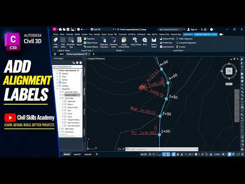
Clear documentation is the backbone of any successful civil engineering project. When designing roads, utilities, or site corridors, properly displaying stations, geometry points, and critical alignment details is essential for constructability. Mastering how to add alignment labels in Autodesk Civil 3D ensures your plan sets remain clean, professional, and easy for field crews to interpret.
Why Alignment Labels Are Essential
Alignment labels automatically display dynamic spatial information along your centerlines, offsets, or profiles. Instead of manually typing station numbers or curve data, these labels pull live information directly from your design model. If your alignment shifts during design revisions, your labels update automatically—saving you hours of manual drafting and reducing costly errors.
Key design information provided by alignment labels includes: - Major and Minor Stations: Clear interval markers along the alignment path. - Geometry Points: Critical transition locations such as Point of Curvature (PC), Point of Tangency (PT), and Point of Intersection (PI). - Design Speed & Superelevation: Vital data required for highway and transportation plans.
Step-by-Step: Adding Alignment Labels in Autodesk Civil 3D
Adding labels to an alignment is a quick and straightforward process:
- Select the Alignment: Click on the alignment in your drawing screen to activate the contextual ribbon.
- Access the Label Menu: Click on the Add Labels dropdown menu and choose Add/Edit Station Labels.
- Select a Label Set: Choose a pre-defined Label Set that contains a group of styles (e.g., Major and Minor Stations with Geometry Points), or add individual label types manually.
- Define Geometry Points: If adding geometry point labels, toggle the specific points you want to display, such as curve entries, midpoints, or tangency changes.
- Apply and Refine: Click Add and then OK to apply the labels to your design.
Best Practices for Clean Annotations
To keep your final construction sheets readable, make full use of label drag states. Utilizing the flexible style management tools within Autodesk Civil 3D allows you to pull labels away from congested areas using leader lines, preventing overlapping text near tight curves or complex intersections.
By incorporating these quick alignment labeling steps into your CAD workflow, you can streamline sheet production and elevate the technical accuracy of your engineering deliverables.


