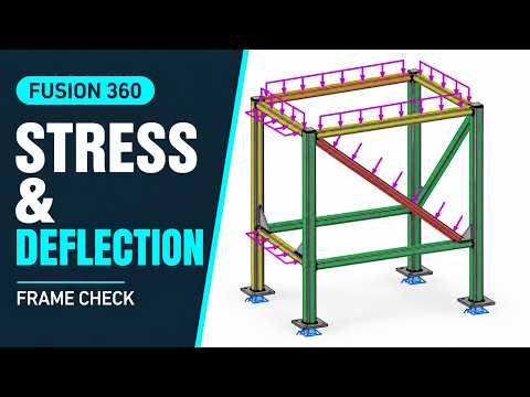
Designing structural frameworks requires absolute confidence in your model's ability to withstand real-world physical forces. Whether you are building heavy industrial machinery, custom vehicle chassis, or architectural supports, evaluating member forces, stress, and deflection is critical to preventing mechanical failure.
With Fusion 360, engineers and product designers have access to an integrated workspace that simplifies structural frame analysis and optimization without requiring complex third-party software.
Why Structural Frame Analysis Matters
Before sending any steel design to manufacturing, you must understand how structural loads behave under real operating conditions. Conducting a comprehensive frame evaluation helps you identify key structural indicators:
- Member Forces: Analyze how axial, shear, and bending forces distribute throughout the framework.
- Stress Concentrations: Locate critical areas where material yielding or structural failure might occur.
- Deflection: Measure the exact distance structural members will bend under applied loads to ensure compliance with safety tolerances.
By testing these parameters early in the design cycle, you significantly cut prototyping costs, minimize excess material, and build safer, more reliable products.
Key Steps for Analyzing Frames
Setting up a simulation workflow is straightforward when using the structural design toolset built into Fusion 360.
- Define Materials and Geometry: Assign standard steel structural profiles to your frame members and verify accurate material properties.
- Apply Constraints and Loads: Set up fixed support points and apply directional forces, live loads, or gravity to reflect actual environment conditions.
- Run the Simulation: Execute the solver to calculate stress distribution, displacement, and load paths across every connected member.
Evaluating Results with Frame Check
Once the simulation completes, interpreting the output is where real design optimization takes place. Utilizing features like Frame Check in Fusion 360, you can review member-by-member performance metrics through clear, color-coded visual overlays.
These visual cues instantly pinpoint excessive stress or unwanted displacement. If a specific structural member shows high deflection, you can modify profile sizes or wall thicknesses in the CAD workspace and immediately rerun the check to verify your improvements.
Conclusion
Integrating simulation into your design workflow bridges the gap between 3D modeling and structural validation. By mastering load, stress, and deflection analysis, you ensure your steel frame designs are efficient, cost-effective, and ready for production.


