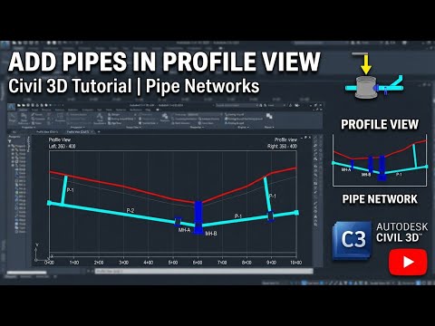
Designing modern infrastructure requires a high level of precision and clear visual documentation. In the world of civil engineering, one of the most critical tasks is ensuring that underground utilities—such as storm drains, sanitary sewers, and water lines—are accurately represented in your profile views. This process is essential for identifying potential utility conflicts and ensuring that slopes and depths meet local regulations. In this guide, we will walk you through the streamlined workflow of displaying these elements using Autodesk Civil 3D.
Step 1: Selecting Your Pipe Network Components
The first step in the process takes place in your plan view. You do not need to manually draw lines or shapes to represent your pipes in a profile; instead, you leverage the intelligent data already present in your model. Simply navigate to your plan view and select the specific pipes and structures you wish to display. You can select them individually or use selection filters to grab an entire pipe run. This intelligent connectivity is one of the primary reasons why Autodesk Civil 3D remains the industry standard for infrastructure design.
Step 2: Utilizing the "Draw Parts in Profile" Command
Once you have selected the desired components of your pipe network, the contextual ribbon at the top of the workspace will update to show options specific to pipe networks. Look for the command labeled "Draw Parts in Profile View." After clicking this button, Civil 3D will prompt you to select the target profile view. Navigate to your profile grid and click on any part of the profile view object (such as the grid or the title). The software will then project the selected pipes and structures into the profile at their correct elevations and slopes automatically.
Step 3: Adjusting Styles and Labels for Clarity
After the parts appear in your profile view, you may need to refine their appearance to suit your project's drafting standards. By right-clicking a pipe or structure within the profile view, you can access the "Pipe Properties" or "Structure Properties" menus. Here, you can change the object style to show the inner or outer walls, apply specific hatch patterns, or display the centerlines. Clear labeling is also vital; adding labels for top-of-pipe elevations or percentage slopes ensures that contractors have all the necessary information for the construction phase.
Conclusion: Streamlining Your Design Workflow
Integrating pipe networks into your profile views is a foundational skill for any civil designer. By mastering these tools within the Autodesk ecosystem, you significantly reduce the risk of manual errors and ensure that your 2D documentation remains perfectly synchronized with your 3D model. This workflow not only saves time during the design phase but also provides a much higher level of accuracy for the final construction documents.


