In the world of civil engineering, precision is paramount. Designing and analyzing pipe networks is a critical component of any land development or municipal project. Autodesk Civil 3D has long been the industry standard for creating these complex systems, but the modern engineer needs more than just drafting tools—they need a connected ecosystem. This is where the power of Autodesk Flow comes into play, helping professionals bridge the gap between design data and actionable analysis.
Getting Started with Pipe Network Analysis
Before jumping into the calculations, it is essential to have a well-defined pipe network. In Civil 3D, this involves setting up your parts list, defining pipe sizes, and establishing the correct surface and alignment references. Once your gravity-fed system—consisting of pipes and structures—is laid out, you can begin the analysis process to ensure the system can handle the anticipated hydraulic loads.
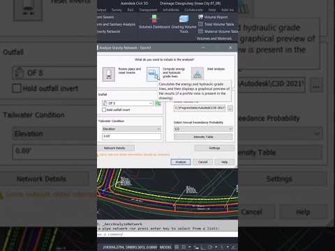
Using the Analyze Gravity Network Tool
Civil 3D provides a built-in "Analyze Gravity Network" wizard that simplifies the hydraulic calculation process. This tool allows you to: * Resize Pipes: Automatically adjust pipe diameters based on flow requirements. * Calculate HGL and EGL: Determine the Hydraulic Grade Line and Energy Grade Line to prevent surcharging. * Check Inverts: Ensure that the slopes are sufficient for gravity flow without causing excessive excavation.
By leveraging Autodesk Flow, designers can better manage the vast amounts of data generated during these stages. This integration ensures that every stakeholder, from the lead engineer to the site contractor, has access to the most up-to-date hydraulic data, reducing the risk of costly errors during construction.
Optimizing Your Workflow
The real advantage of performing analysis within the Civil 3D environment is the dynamic nature of the software. If a site plan changes and a structure moves, the analysis can be re-run instantly. This iterative process is a core component of the Autodesk Flow philosophy—creating a seamless stream of information that moves through the project lifecycle.
Instead of exporting data to external spreadsheets and losing the "source of truth," keeping your analysis integrated allows for better visualization. You can see your HGL directly in profile views, making it easier to identify bottlenecks or potential overflows before they become real-world problems.
Conclusion
Mastering pipe network analysis in Civil 3D is about more than just clicking buttons; it’s about understanding how water moves through your design. By adopting a modern workflow and utilizing the connectivity provided by Autodesk Flow, you can deliver safer, more efficient, and more sustainable infrastructure projects. Whether you are a seasoned professional or a student, refining these skills will significantly enhance your value in the AEC industry.


