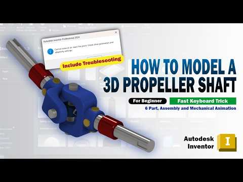
Are you looking to sharpen your mechanical design skills and master complex 3D assemblies? Learning how to model functional mechanical components is an essential milestone for any student, engineer, or CAD enthusiast. In this comprehensive guide, we walk you through the process of modeling and assembling a Universal Joint—a fundamental component used in automotive and industrial applications to transmit rotary motion between non-parallel shafts.
Understanding the Universal Joint Components
Before opening your 3D workspace, it is helpful to understand the basic anatomy of a universal joint (U-joint). A standard assembly consists of three primary elements: * Two Y-Shaped Yokes: These driving and driven components attach to the rotating shafts. * The Central Cross (Spider): The core block that connects both yokes and allows multidirectional flexibility. * Fasteners and Pins: Components that lock the assembly together while permitting smooth rotation.
Accurate dimensions and clearance checks are vital during the modeling phase to ensure all parts fit together without mechanical interference.
Building the Assembly in Autodesk Inventor
Creating a dynamic mechanical system requires a structured workflow. Utilizing Autodesk Inventor, you can effortlessly transition from individual 2D sketches to a fully articulated 3D model. Here is an overview of the key steps:
- Part Modeling: Begin by sketching the base profiles for the yokes and the center cross. Use standard features like extrude, revolve, and fillet to form the solid bodies, ensuring all dimensions are fully constrained.
- Applying Constraints and Joints: Import all finished parts into an assembly file within Autodesk Inventor. Instead of basic mate constraints, use dynamic joint relationships (such as rotational joints) to define exact mechanical interactions between the cross and the yokes.
- Motion Verification: Test the complete mechanism by rotating the input shaft. Observing the continuous angular drive helps verify that your rotational constraints function accurately in 3D space.
Pro Tips for Efficient 3D Modeling
To optimize your design workflow, always maintain a clean feature tree and name your key parameters logically. Taking advantage of the advanced assembly tools in Autodesk Inventor allows you to detect potential physical collisions early in the design phase, reducing errors before reaching the manufacturing stage.
Final Thoughts
Mastering the creation of a universal joint assembly is an excellent way to elevate your 3D modeling expertise. By applying these parametric techniques, you will gain the confidence needed to tackle far more intricate mechanical systems in your future projects.


