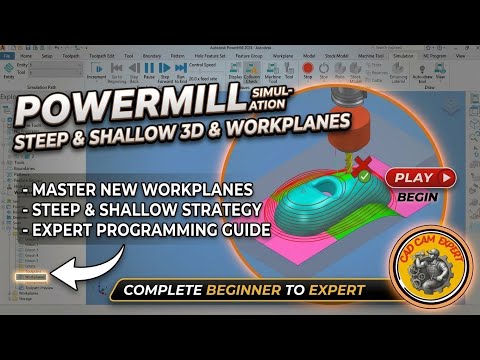
Whether you are a seasoned CNC programmer or just stepping into advanced manufacturing, mastering professional CAM software is crucial for producing high-precision components. Autodesk PowerMill stands out as one of the most powerful solutions for high-speed, multi-axis, and complex 3D surface machining.
In this guide, we break down two essential techniques that every CNC machinist should master: proper workplane setup and the highly efficient Steep and Shallow 3D machining strategy.
The Importance of Accurate Workplane Setup
A successful machining operation always begins with an accurate origin. Setting up a new workplane correctly in Autodesk PowerMill allows you to align your part model precisely with your CNC machine's coordinate system.
When defining a new workplane, keep these key factors in mind: - Part Orientation: Align the tool axis perpendicular to the primary machining surface to ensure stability and accuracy. - Datum Points: Select logical reference points—such as model corners or center bores—that can be easily located on the physical stock during machine setup. - Clearance Planes: Define clear safe heights to prevent costly tool collisions during rapid transfer moves.
Proper workplane management minimizes setup errors on the shop floor, saves programming time, and ensures smooth multi-axis indexing.
Optimizing Surface Finish with Steep and Shallow Machining
One of the biggest challenges in 3D surface milling is handling complex geometry that features both steep vertical walls and flat, shallow regions. Using a single traditional toolpath strategy across the entire part often results in uneven surface finishes and inefficient cutting conditions.
The Steep and Shallow machining strategy in Autodesk PowerMill solves this challenge by intelligently splitting the target geometry based on a specified threshold angle: - Steep Regions: Automatically applies Z-level (contouring) toolpaths to maintain constant stepdowns on vertical or steep walls. - Shallow Regions: Uses optimized raster or offset patterns across flat or low-incline surfaces to eliminate step marks.
By combining these two approaches into a unified toolpath, you maximize surface quality while significantly reducing overall cycle time and cutter wear.
Final Thoughts
Mastering proper workplane alignment alongside versatile strategies like Steep and Shallow 3D machining will significantly elevate your CAM workflow. Implementing these best practices ensures consistent surface finishes, longer tool life, and peak productivity on your machine shop floor.


