Achieving accurate injection molding simulation results starts with a flawless mesh. When analyzing complex plastic parts using Autodesk Moldflow, engineers often encounter various mesh diagnostic warnings. One of the most critical yet frequently misunderstood issues is the Connectivity Region error. Understanding what connectivity regions are and how to fix them efficiently can significantly improve your simulation speed and accuracy.
What is a Connectivity Region?
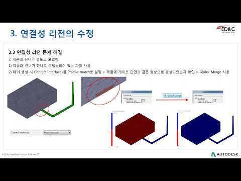
A Connectivity Region refers to a group of mesh elements that are continuously connected to one another but disconnected from the rest of the model's mesh network. In simple terms, if your model contains two or more isolated mesh groups, the software registers them as separate connectivity regions. For a successful filling, packing, or cooling simulation, a single solid plastic component must exist as one contiguous mesh network.
Common Causes of Connectivity Errors
Why do these isolated regions appear in your model during preprocessing? The most common causes include: * CAD Surface Flaws: Tiny gaps, overlapping surfaces, or unstitched edges present in the original CAD geometry. * Incomplete Manual Editing: Deleting or stitching elements without properly connecting surrounding nodes. * Stray or Floating Elements: Isolated node clusters or duplicate elements left behind after mesh generation.
How to Fix Connectivity Region Issues
Resolving mesh connectivity errors in Autodesk Moldflow is straightforward when you follow a structured troubleshooting workflow:
- Run the Connectivity Diagnostic: Use the Mesh Diagnostic tool to display connected mesh groups visually. If the system highlights multiple color-coded regions on a single part, isolated mesh sections exist.
- Locate and Inspect Secondary Regions: Zoom in on smaller, secondary connectivity regions. These are frequently floating stray elements or unattached surfaces hidden inside or near the main body.
- Merge Nodes or Delete Unattached Elements: Use the Merge Nodes or Stitch tools to bridge small physical gaps. If the isolated region consists of unwanted artifacts or duplicate elements, select and delete them directly.
- Re-mesh Problematic Areas: After fixing local gaps, re-mesh the affected region to guarantee a smooth element density transition across connected boundaries.
Conclusion
By maintaining proper mesh continuity in Autodesk Moldflow, you prevent solver failures and ensure highly reliable flow and warpage predictions. Integrating these simple mesh troubleshooting techniques into your workflow will save valuable preparation time and boost the accuracy of your engineering analysis.


